
I've recently posted a quick post on LinkedIn about a feature from FortiOS 6.2. It turned out I've received many private messages asking for more in-depth information. Hence this article.
Let's dissect a bit how we could leverage this on FortiOS:
Using set encapsulation vxlan on an IPsec phase1 was created for the simple case of connecting two LANs via IPsec+VXLAN.
If our goal is more complicated, such as wanting to separate vLANs over VXLAN then set encapsulation vxlan is not the solution. Instead we should use config system vxlan and bind that interface to an ipsec-phase1 interface.
Now that we have this in mind, let's detail a bit what we'll need in order to succeed in our orginial goal of having vLANs inside VXLAN over IPsec.
1st things 1st we'll need our IPsec underneath layer to be up and running, i've setup that as a simple custom site to site connection in this lab.
config vpn ipsec phase1-interface
    edit "to_SITE2"
        set interface "port10"
        set ike-version 2
        set peertype any
        set net-device disable
        set proposal ...
        set dhgrp ...
        set remote-gw 192.168.166.22
        set psksecret ghost
    next
end
config vpn ipsec phase2-interface
    edit "to_SITE2"
        set phase1name "to_SITE2"
        set proposal ...
        set dhgrp ...
    next
end
Of course, we'll need a set of IPsec enabler policies in order to bring our tunnel up.
config firewall policy
    edit 50
        set name "SITE1-to-SITE2_IPsec_enabler"
        set srcintf "to_SITE2"
        set dstintf "to_SITE2"
        set srcaddr "all"
        set dstaddr "all"
        set action accept
        set schedule "always"
        set service "ALL_ICMP"
        set logtraffic all
        set logtraffic-start enable
    next
We can now move on to our next configuration tasks, add IP overlays on our IPsec interface and bind our VXLAN interface on the remote peer overlay IP (representations here applies to "Site1", same config are needed on both sites).
   config system interface
       edit "to_SITE2"
            set vdom "root"
            set ip 10.1.1.1 255.255.255.255
            set allowaccess ping
            set type tunnel
            set remote-ip 10.1.1.2 255.255.255.255
            set snmp-index 12
            set interface "port10"
        next
    config system vxlan
        edit "vxlan"
            set interface "to_SITE2"
            set vni 1000
            set remote-ip "10.1.1.2"
        next
    end
    config system interface
        edit "vxlan"
        set vdom "root"
        set type vxlan
        set snmp-index 13
        set interface "to_SITE2"
    next
What do we have now, our IPsec tunnel, our VXLAN interface bound to it (on the remote overlay IP per site). And here is what you shall see on a GUI perspective:

Now comes the fun part, what we want is to embed vLANs within VXLAN, let's setup a few vLANs interfaces we'll want to L2 extend over VXLAN. We will setup two vLAN interface per wanted vLANs, one bound on our local physical interfaces (vlan444/port2) and another instance (vxlan444/vxlan) bound on our VXLAN interface previously setup. Same applies to our next vlan, vlan555.
config system interface
    edit "vlan444"
        set vdom "root"
        set alias "vlan444"
        set device-identification enable
        set role lan
        set snmp-index 15
        set interface "port2"
        set vlanid 444
    next
    edit "vxlan444"
        set vdom "root"
        set device-identification enable
        set role lan
        set snmp-index 24
        set interface "vxlan"
        set vlanid 444
    next
    edit "vlan555"
        set vdom "root"
        set alias "vlan555"
        set device-identification enable
        set role lan
        set snmp-index 25
        set interface "port2"
        set vlanid 555
    next
    edit "vxlan555"
        set vdom "root"
        set device-identification enable
        set role lan
        set snmp-index 26
        set interface "vxlan"
        set vlanid 555
    next
Now, in order to bridge these vLANs over VXLAN, we need to leverage the use of software switches, used as pure bridges between local vLANs and VXLAN bound vLANs (vlan444/vxlan444).
config system switch-interface
    edit "br-444-s1"
        set vdom "root"
        set member "vlan444" "vxlan444"
    next
    edit "br-555-s1"
        set vdom "root"
        set member "vlan555" "vxlan555"
    next
end
config system interface
    edit "br-444-s1"
        set vdom "root"
        set ip 10.10.44.254 255.255.255.0
        set allowaccess ping
        set type switch
    next
    edit "br-555-s1"
        set vdom "root"
        set ip 10.10.55.254 255.255.255.0
        set allowaccess ping
        set type switch
    next
In my setup, the bridge interfaces are the local gateways from each vLANs. Here is what my GUI gives me with this configuration:
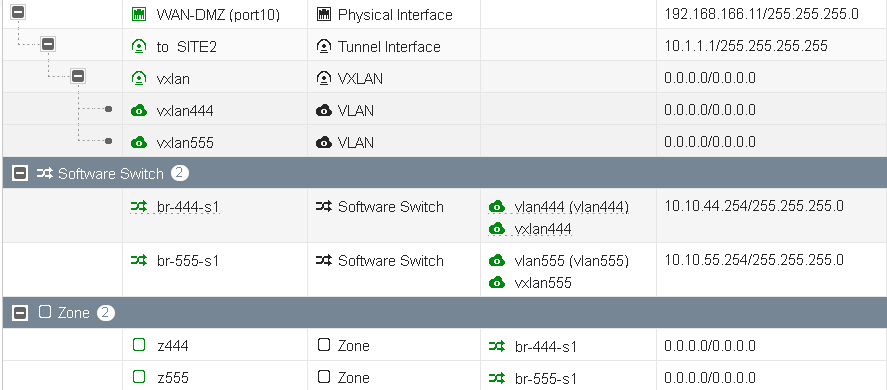
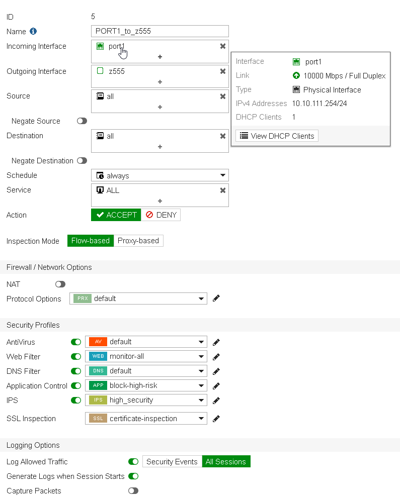
As usual, I'm using Zones within my firewall policies, I like them because they give me another abstraction layer meaning that i can change physical properties without changing firewall policies themselves.
A view from a firewall policy from port1 (where a Kali host is sitting, 10.10.111.100, this on site1).
And a view from the Kali box reaching VXLAN extended vLANs resources over IPsec:
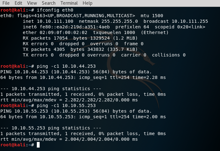
.253 are my software switch resources sitting on Site2 respectively for vLAN444 and vLAN555.
One of the advantages of using such configuration to me is that you'll have possibilities to invoke UTM modules (App Control, IPS, ect.) between VXLAN extended vLANs (for example, vlan444 to vlan555 etc).
Hope you've found this interesting. Do not hestitate to reach out to me per email, available on my profile view below.
Kind regards,
Obuno